Sunday, 3 November 2019

COLLIMATION ERROR AND HOW TO CORRECT THE COLLIMATION ERROR

1. Error of Collimation:

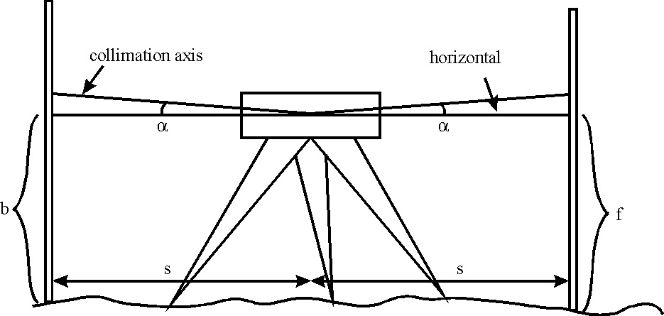
Collimation error occurs when the collimation axis is not truly horizontal when the instrument is level. The effect is illustrated in the sketch below, where the collimation axis is tilted with respect to the horizontal by an angle a:
Error of Collimation                                                                                                                                                       2. CORRECTION                                                                                                         This type of error can be eliminated by placing the levelling instrument at  midway between two points .due to collimation error we normally get either upward slop or downward slop                                                                                                                                                  

ERRORS IN LEVELLING

1. Instrumental Errors:

(i) Imperfect adjustment:
ADVERTISEMENTS:
The essential requirement in levelling is that the line of collimation must be horizontal when the instrument is levelled. If the level is in perfect adjustment, the line of collimation is parallel to the bubble axis so that it becomes horizontal when the bubble is centred.
If the adjustment is not correct, the line of collimation will be inclined even though the bubble is central. The error due to the inclination of the line of collimation is proportional to the distance of the staff from the instrument.
This is most common and serious source of error, it can be eliminated:
(a) Testing and adjusting the instrument, and
(b) By equalising the back sight foresight distances.
(ii) Defective level tube:
If the bubble is sluggish, it may remain in centre even though the bubble axis is not horizontal. And if it is over sensitive, much time is wasted in levelling the instrument. Therefore the level tube fitted with the level should be only of the required sensitiveness.
(iii) Shaky tripod:
A shaky tripod renders the instrument unstable and thus leads to erroneous readings. The tripod should therefore be examined and loose joints be tightened.
(iv) Incorrect graduations of the staff:
When the staff is new one, the graduations should be checked up with an invar tape as there is every possibility of error in graduating the staff. It is however negligible in ordinary work.                    

 2. Errors of Manipulation:

 (i) Careless levelling-up of the instrument:
ADVERTISEMENTS:
The instrument should be accurately levelled and the hand should not rest on the telescope or tripod while taking the readings.
(ii) The bubble not being central at the time of taking reading:
This is the most serious and common source of error. The position of the bubble should be checked just before and after each reading is taken. The bubble should be brought in the centre of its run, if necessary, by means of a levelling screw most nearly in line with the telescope.
(iii) The parallax not removed properly:
ADVERTISEMENTS:
This error is due to imperfect focussing of the eye-piece and of the object-glass. The parallax should be entirely elimination by proper focussing before taking any reading.
(iv) The staff not being held vertical:
If the staff is not held perfectly vertical, the reading obtained will always be too great. This error is much pronounced for greater readings of staff, the greater the staff reading, the greater is the error. Great care should, therefore, be taken when taking larger readings. This error can be avoided by keeping the staff vertical by having a spirit level or a pendulum plumb-bob attached to the staff or by waving the staff and noting the smallest reading.                                                                   

3. Error due to Natural Causes:

(i) Curvature and refraction:
The effect of curvature of the earth is to cause the objects sighted lower than they actually are while that of the refraction is to make them appear higher than they actually are. In ordinary levelling , the error due to curvature and refraction need not be taken into consideration, since it is very small and hence negligible (only 0.003 m for a 200 m sight-length). For long sights, the correction for curvature and refraction has to be applied.
(ii) Wind:
It is difficult to perform accurate work in a wind storm because of the vibration of the instrument. If levelling is necessarily to be performed during wind , adequate arrangements should be made to shelter the instrument and larger readings should be avoided due to difficulty in holding the staff vertical.
(iii) Sun:
On hot sunny days, during the mid-day hours, the staff appears trembling near the ground and taking the correct readings becomes impossible. The work should therefore be suspended during hot hours. If this is not possible, the line of sight should be kept as much above the ground as possible and the length of sight kept short . Also ray-shade should be used if the Sun shines on the object glass.                                                                                                                                                                                                                                                                 

Thursday, 31 October 2019

WHAT IS BEAM AND IT'S TYPES

A beam is a structural member used for bearing loads. It is typically used for resisting vertical loads, shear forces and bending moments.
According to its requirement, different beams use in different conditions like fix beam, cantilever beam etc.
Types of beams:
Beams are classified as follow.
According to end support:
1. Simply Supported Beam:
As the name implies, simply supported beam is supported at both end. One end of the beam is supported by hinge support and other one by roller support. This support allow to horizontal movement of beam. It beam type undergoes both shear stress and bending moment.
2. Continuous Beams:
When we talk about types of beams we cannot forgot continuous beam. This beam is similar to simply supported beam except more than two support are used on it. One end of it is supported by hinged support and other one is roller support. One or more supports are use between these beams. It is used in long concrete bridges where length of bridge is too large.
3. Overhanging Beams:
Overhanging beam is combination of simply supported beam and cantilever beam. One or both of end overhang of this beam. This beam is supported by roller support between two ends. This type of beam has heritage properties of cantilever and simply supported beam.
4. Cantilever Beams:
Cantilever beams a structure member of which one end is fixed and other is free. This is one of the famous type of beam use in trusses, bridges and other structure member. This beam carry load over the span which undergoes both shear stress and bending moment.
5. Fixed beams:
This beam is fixed from both ends. It does not allow vertical movement and rotation of the beam. It is only under shear stress and no moment produces in this beams. It is used in trusses, and other structure.
According to cross section:
A beam may have different cross section. The most common cross section of beam are as follow.
1. I beam:
This beam types have I cross section as shown in figure. It has high resistance of bending.
2. T beam:
It has T cross section as shown in figure.
According to equilibrium condition:
1. Statically determinate beam:
A beam is called determinate beam if it can be analyze by the basic equilibrium condition. The support reaction can be found by using basic equilibrium condition. These conditions are
Summation of all horizontal forces is zero.
Summation of all vertical forces is zero.
Summation of all moments is zero.
Example: Simply supported beam, Cantilever beam etc.
2. Statically indeterminate beam:
If the beam cannot be analysis by using basic equilibrium condition, known as statically indeterminate beam. The end reaction find out by using basic equilibrium condition with combination of other conditions like strain energy method, virtual work method etc.
Example: Continuous beam, fixed beam
According to Geometry:
1. Straight beam
2. Curved beam
3. Tapper beam.

Wednesday, 30 October 2019

NORTON'S THEOREM

Norton’s theorem is similar to Thevenin’s theorem. It states that any two terminal linear network or circuit can be represented with an equivalent network or circuit, which consists of a current source in parallel with a resistor. It is known as Norton’s equivalent circuit. A linear circuit may contain independent sources, dependent sources and resistors.
If a circuit has multiple independent sources, dependent sources, and resistors, then the response in an element can be easily found by replacing the entire network to the left of that element with a Norton’s equivalent circuit.
The response in an element can be the voltage across that element, current flowing through that element or power dissipated across that element.
This concept is illustrated in following figures.
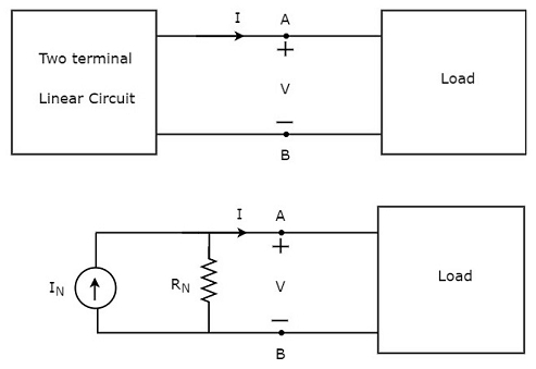
Response in a Element
Norton’s equivalent circuit resembles a practical current source. Hence, it is having a current source in parallel with a resistor.
  • The current source present in the Norton’s equivalent circuit is called as Norton’s equivalent current or simply Norton’s current IN.
  • The resistor present in the Norton’s equivalent circuit is called as Norton’s equivalent resistor or simply Norton’s resistor RN.

Methods of Finding Norton’s Equivalent Circuit

There are three methods for finding a Norton’s equivalent circuit. Based on the type of sources that are present in the network, we can choose one of these three methods. Now, let us discuss these three methods one by one.

Method 1

Follow these steps in order to find the Norton’s equivalent circuit, when only the sources of independent type are present.
  • Step 1 − Consider the circuit diagram by opening the terminals with respect to which, the Norton’s equivalent circuit is to be found.
  • Step 2 − Find the Norton’s current IN by shorting the two opened terminals of the above circuit.
  • Step 3 − Find the Norton’s resistance RN across the open terminals of the circuit considered in Step1 by eliminating the independent sources present in it. Norton’s resistance RN will be same as that of Thevenin’s resistance RTh.
  • Step 4 − Draw the Norton’s equivalent circuit by connecting a Norton’s current IN in parallel with Norton’s resistance RN.
Now, we can find the response in an element that lies to the right side of Norton’s equivalent circuit.

Method 2

Follow these steps in order to find the Norton’s equivalent circuit, when the sources of both independent type and dependent type are present.
  • Step 1 − Consider the circuit diagram by opening the terminals with respect to which the Norton’s equivalent circuit is to be found.
  • Step 2 − Find the open circuit voltage VOC across the open terminals of the above circuit.
  • Step 3 − Find the Norton’s current IN by shorting the two opened terminals of the above circuit.
  • Step 4 − Find Norton’s resistance RN by using the following formula.
RN=VOCIN

  • Step 5 − Draw the Norton’s equivalent circuit by connecting a Norton’s current IN in parallel with Norton’s resistance RN.
Now, we can find the response in an element that lies to the right side of Norton’s equivalent circuit.

Method 3

This is an alternate method for finding a Norton’s equivalent circuit.
  • Step 1 − Find a Thevenin’s equivalent circuit between the desired two terminals. We know that it consists of a Thevenin’s voltage source, VTh and Thevenin’s resistor, RTh.
  • Step 2 − Apply source transformation technique to the above Thevenin’s equivalent circuit. We will get the Norton’s equivalent circuit. Here,
Norton’s current,
IN=VThRTh

Norton’s resistance,
RN=RTh

This concept is illustrated in the following figure.
Source Transformation
Now, we can find the response in an element by placing Norton’s equivalent circuit to the left of that element.
Note − Similarly, we can find the Thevenin’s equivalent circuit by finding a Norton’s equivalent circuit first and then apply source transformation technique to it. This concept is illustrated in the following figure.
Technique
This is the Method 3 for finding a Thevenin’s equivalent circuit.

Example

Find the current flowing through 20 Ω resistor by first finding a Norton’s equivalent circuit to the left of terminals A and B.
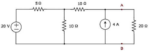
Example Problem
Let us solve this problem using Method 3.
Step 1 − In previous chapter, we calculated the Thevenin’s equivalent circuit to the left side of terminals A & B. We can use this circuit now. It is shown in the following figure.
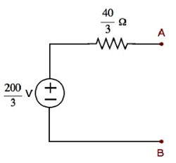
Resistance
Here, Thevenin’s voltage, VTh=2003V and Thevenin’s resistance, RTh=403Ω
Step 2 − Apply source transformation technique to the above Thevenin’s equivalent circuit. Substitute the values of VTh and RTh in the following formula of Norton’s current.
IN=VThRTh

IN=2003403=5A

Therefore, Norton’s current IN is 5 A.
We know that Norton’s resistance, RN is same as that of Thevenin’s resistance RTh.
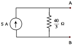
RN=403Ω

The Norton’s equivalent circuit corresponding to the above Thevenin’s equivalent circuit is shown in the following figure.
Norton’s Circuit
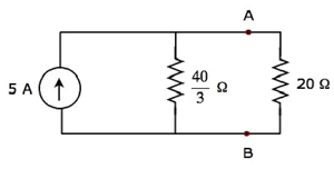
Now, place the Norton’s equivalent circuit to the left of the terminals A & B of the given circuit.
Terminals
By using current division principle, the current flowing through the 20 Ω resistor will be
I20Ω=5403403+20

I20Ω=540100=2A

Therefore, the current flowing through the 20 Ω resistor is 2 A.